HK-4225 Build and Review (by Dr. Ralph Okon, AKA PowerCroco)
© Dr. Ralph Okon 17.04.2010
translated by Pierre Mousel
The powerlimits of this motor are depending on the skill of the assembler, but if you do well it will be a lot more than the stock motor sold in the market.
8 kW peak power are possible and already tested.
Some videos of well-known German helicopter pilots with different wound HK 42xx issued from these kits:
Timo Wendland
Christian Samuelis
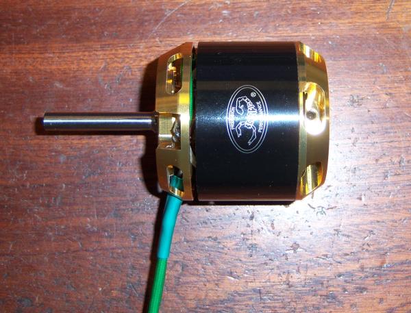
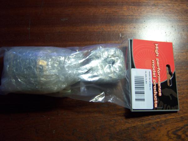 This it how it comes out of the box.
 Well packed and protected.
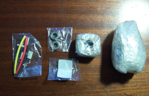
Inside the packing:
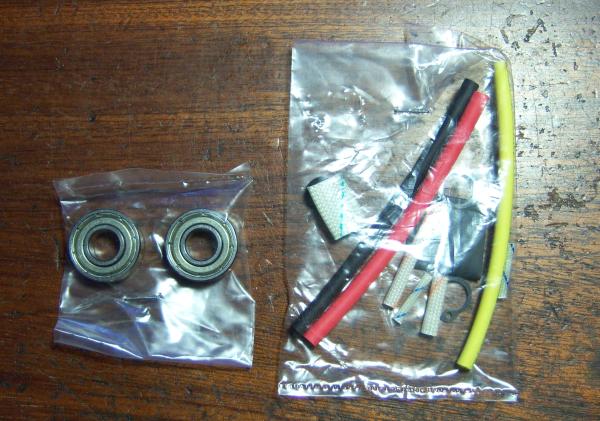
Details of the small parts bag.
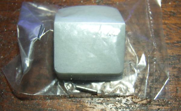 The 1.5mm (~1/16”) anti rotation pin.
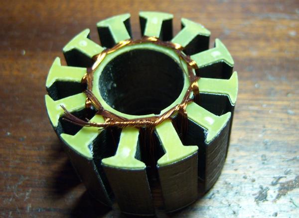
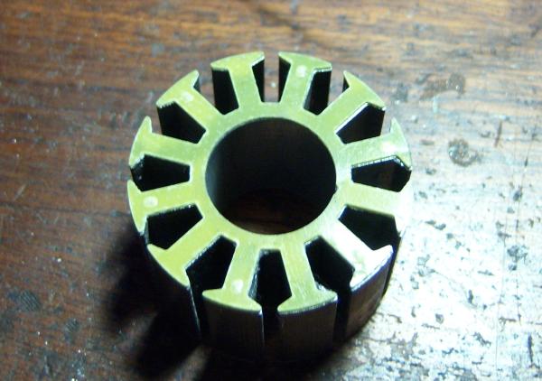
The stator plates have dimples made during fabrication process to allow a perfect positioning.
The glass fiber insulation plates are already glued on the stator package.
Unfortunately in this sample kit, the fiber plates were not correctly positioned.
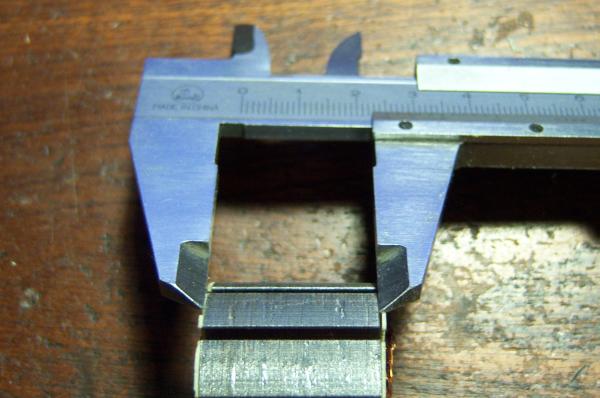 The stator package made of 0.2mm ( ~80mil ) steel is exactly 25mm ( ~1”) high, on top to be added thickness of the insulating plates.
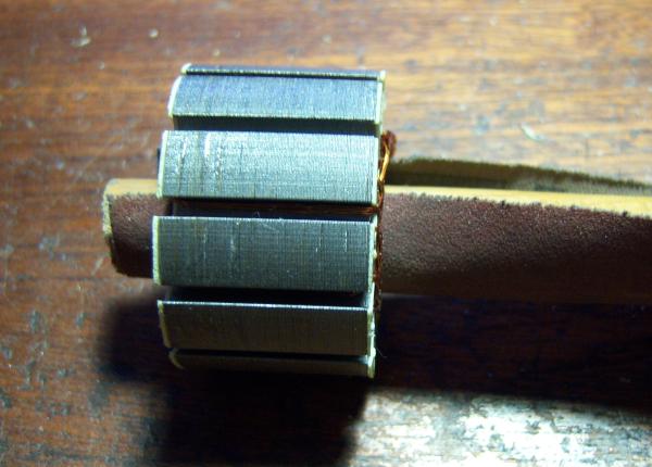
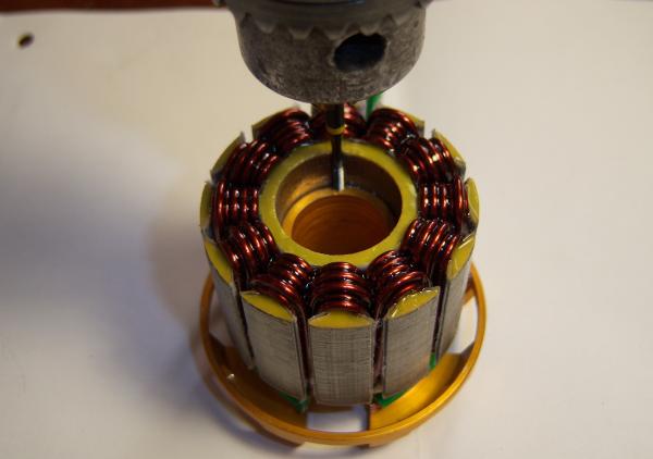
First operation is to make the bounded (don’t remove the wires) stator package match the holder body.
To do this, let’s fix some sanding paper to a matching round wood and remove all the steps and remains inside the stator bore.
 Also the stator holder requires some work until the stator package and the holder are in a perfect match. Don’t remove too much, a neatly firm match is requested.
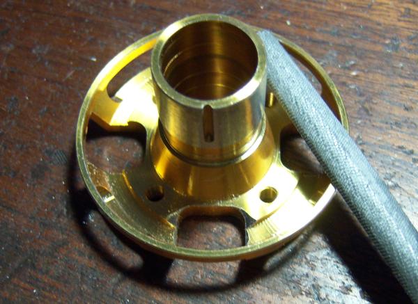
On the hole of the back plate where the wire will go out you need to round the edges of the machined hole. In this example a small round file is used. This is to avoid shorts during operations due to vibrations.

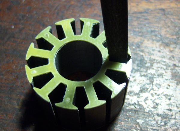
Now you can remove the wire wound around the stator package.
Handle with care from now on in order to avoid splits in the package.
If this occurs, re-glue with thin CA
Do this only is you experience the problem shown in 6!!
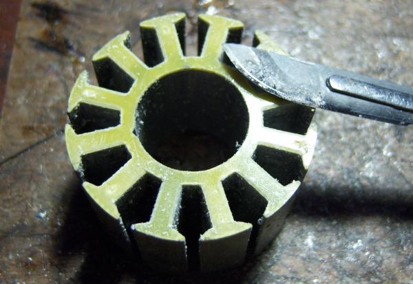
Remove the insulation by inserting a sharp knife between plate and stator package. Normally the insulation plate will split of.
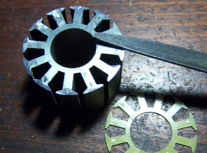 As I had to remove the insulation plates, I took the occasion to remove the positioning dimples from the side there they stand out of the last stator plate.
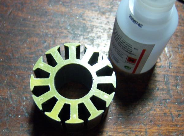 Use thin CA to re-glue the insulation plates..
The thin CA will spread very well under the insulation plate due to capillarity.
I tock the habit to clean the slots with a small flat file.
Take care to hold or fix the stator package firmly in order not to split off the insulation plates..
Then trim all the edges of the insulation plates. I use a sharp scalpel to scrap the edges at a ~45 ° angle.
The insulation paper for the first winding group is in place on this picture.
I recommend to newbie’s to fix the paper with a drop of thick CA in the slot ground. It will prevent the paper from slipping out of the slot during the winding.
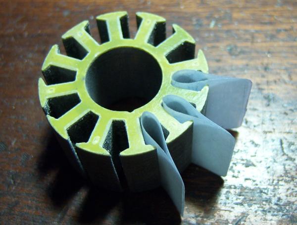
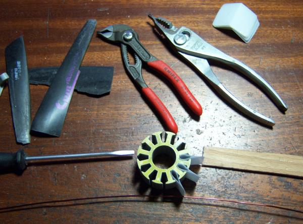 The actual tool gallery:
The propeller blades (recycled) must be of carbon fiber reinforced plastic.
Laminated propellers are not suitable as they contain glass fibers cloth that will damage the wire insulation.
Prohibited also are any glass fiber reinforced tools.
On the screwdriver and the modified pliers all edges are sanded of with 400 -> 800 -> 1200 sanding paper and polished until there are no remaining sharp edges.
There must be no scratch on the wire insulation if you run a copper wire over them.
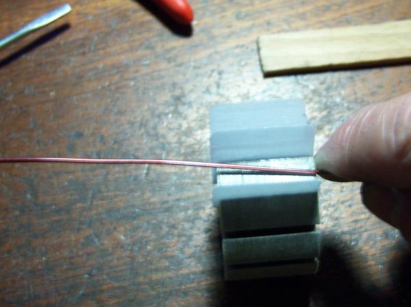
Take the first wire and fix the distance for the outside connections.
Bend the first radius outside of the stator block over a tapered hardwood or plastic square stick.
This buckle is inserted into the stator block and is the first half winding.
Before making the windings, please note that there is no difference if you work clockwise or counter-clockwise.
The following winding is only an example; different variants are possible and also useful.
If you realize an YY winding with identical small groups, the best is to start in the slot near the fixation groove of the stator package.
To realize a YY winding, the starting remaining wire lengths should be at least as follows:
Group 1 - Long starting wire ~5”
Group 2 - Short starting wire ~2”
Group 3 - Long starting wire ~6”
Group 4 - Short starting wire ~2 1/2”
Group 5 - Long starting wire ~6”
Group 6 - Short starting wire ~2”
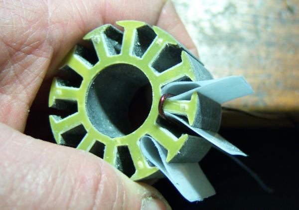
I start winding from “outside”, means on the left side you see the start of the winding group and between the teeth’s the preliminary end.
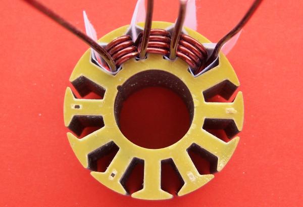
The first tooth of the second group finished.
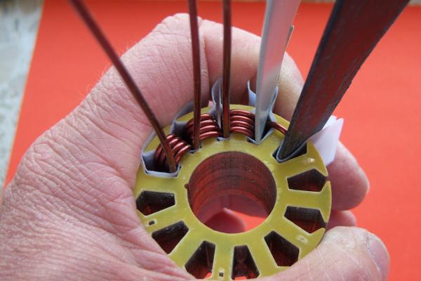
Here you see how to use the propeller blade to flatten the winding.
If you use the screwdriver, apply some insulation paper between wire and blade in order to avoid damages on the wire insulation.
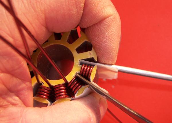
The modified pliers are used as shown on the picture.
This only works fine if the rework has been very meticulous and absolutely no sharp edges are remaining on the pliers.
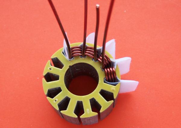
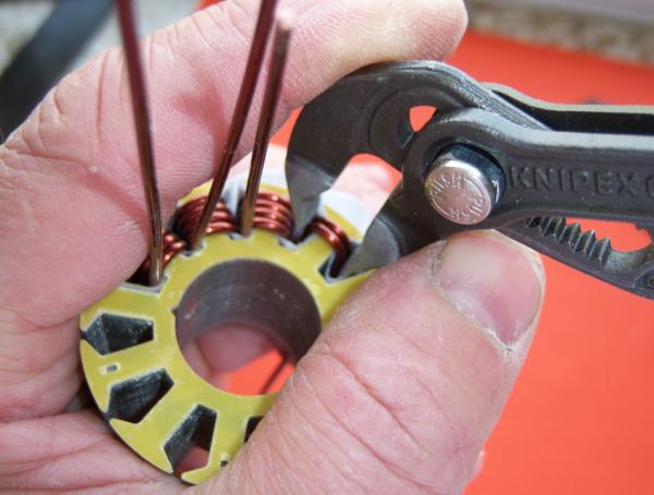
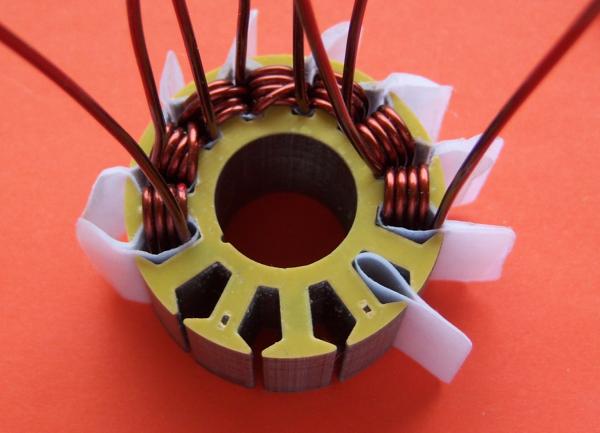
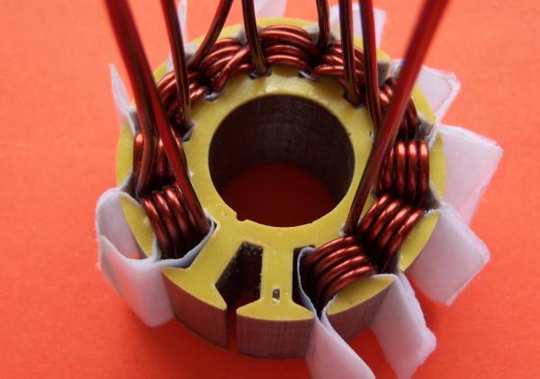
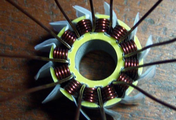
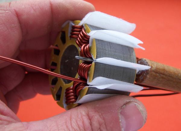
The second winding group is finished now.
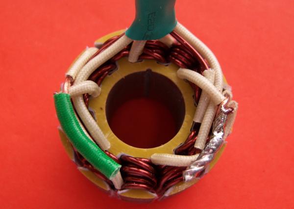
The 2 finished groups seen from front.
Please note: The fixation groove is on the left; the groove you see on the right is the groove in the insulation plate that was not well positioned during re-gluing.
The small winding groups here are realized in 6+5 windings as the finished stator is planned with 7+6 YY. Don’t be puzzled now.
The explanation will follow later.
The first tooth of winding group 3 is finished.
The winding group 3 is done.
If you want, you can already now add the extra top windings ( zig-zag) if the neighborhood teeth are finished with the first layer. This can also bee done at the end when all teeth's are wound with the first layer.
Seen from the front.
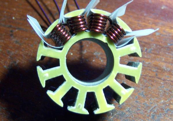
The 4th group is finished.
Picture shows group 1 to 4 finished with first tooth of group 5.
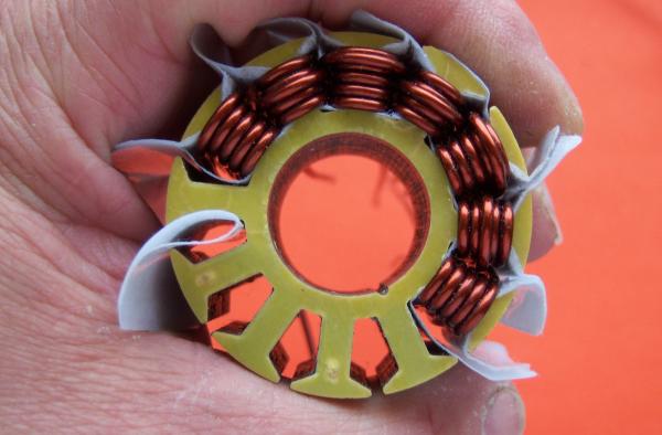
5 finished groups seen from front.
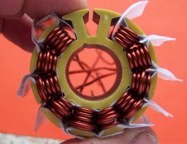
And from the back.
Only one tooth remaining.
The first layer is almost finished, but without the extra top winding ( zig-zag).And from the back.
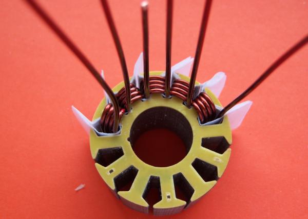
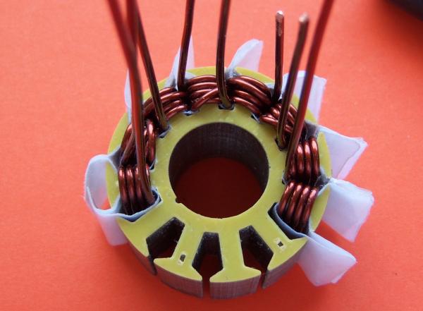
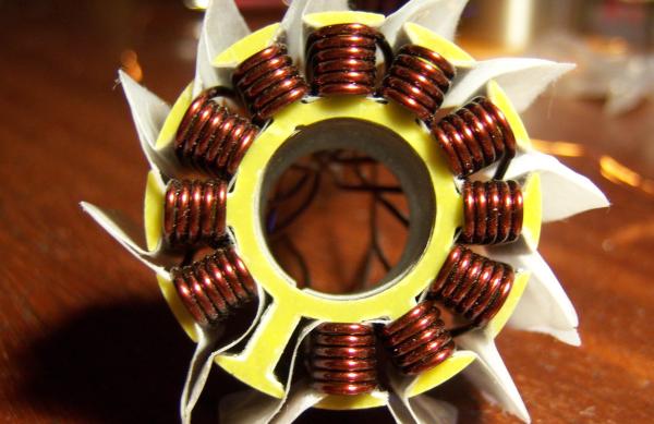
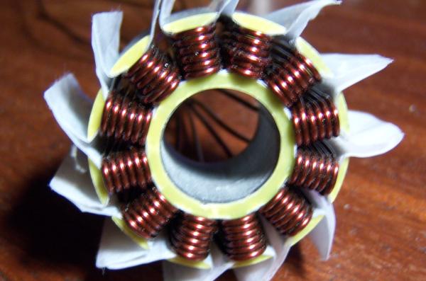
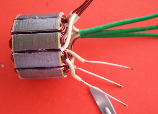
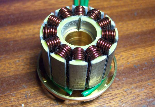
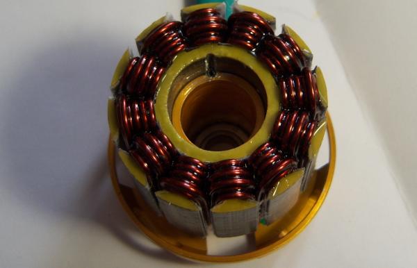
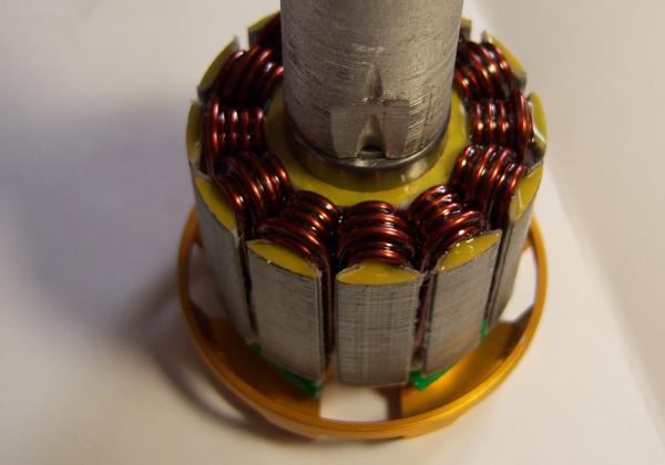
All teeth’s finished.
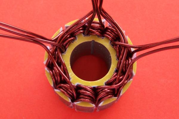
From the front you can see alternating 5 and 6 wire buckles and 11 wires in every slot
Seen from the back, there must be a wire end in every slot.
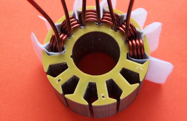
If you realize now the extra top windings all together, take the end of every group and ad a winding to the tooth that has actually 5 windings.
It will fit normally between the existing winding.
Every tooth has now 6 windings, means 12 wires in every slot.
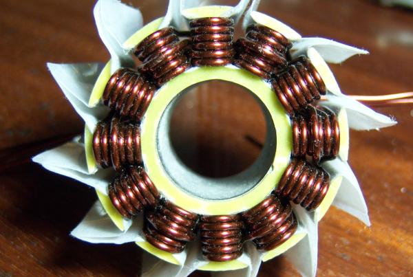
If you add the seventh winding on the first tooth where you have added the 6th one or on the neighbor tooth with initially 6 windings is electrically without any difference.
It is solely the personal preference of the winder, in this example the extra windings are in an 8 pattern (5+6 gives finally 6+7)
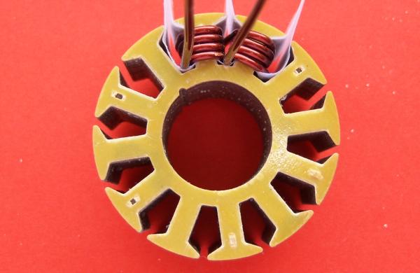
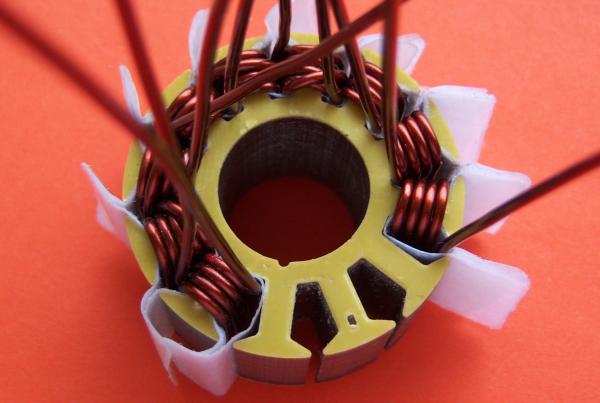
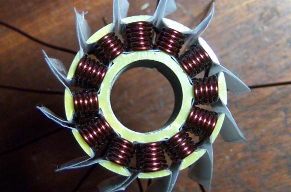
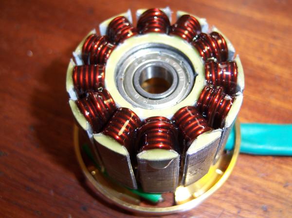
The groups are fully finished now.
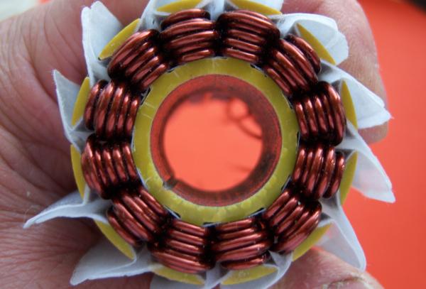
Another possible winding: Here you see 6+7 1.32YY. Done with groups of 5 + 5 + 2 zig + 1 zag
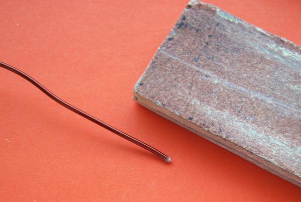
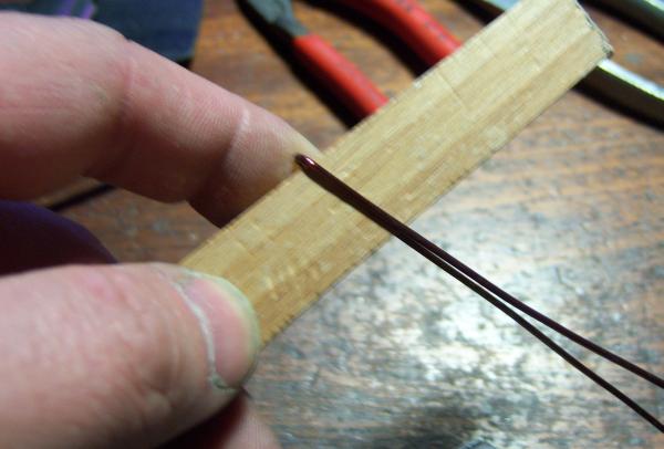
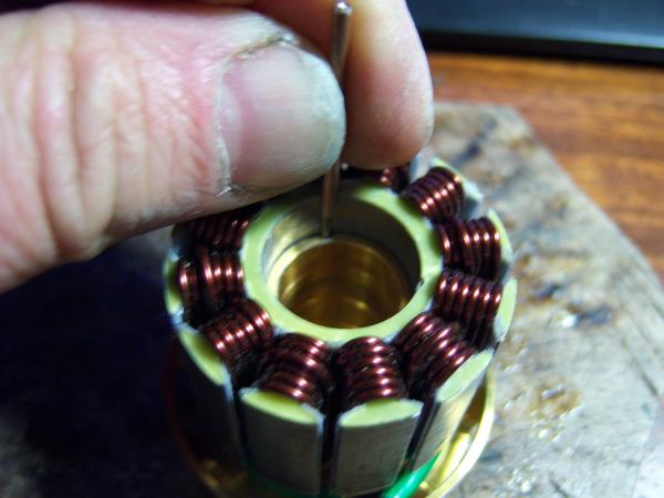
To ease the induction between the teeth’s, it is strongly recommended to round the end of the wire in order to avoid damages on the already done winding.
The copper wire edges are sharp and can damage our winding insulation.
The needle (without sharp tip) is use as to make way for the wire as seen on the picture.
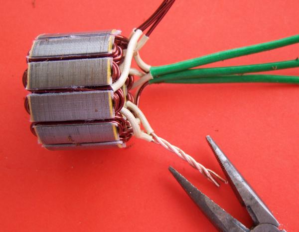
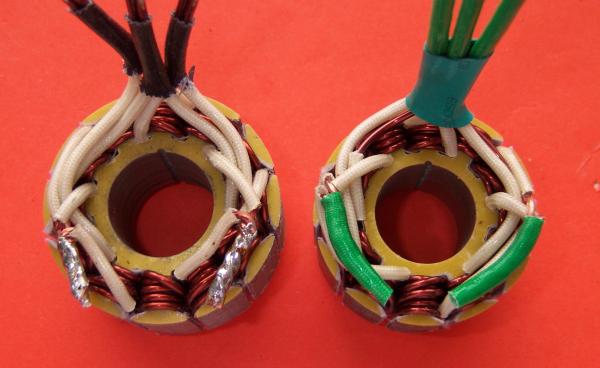
Here you see the preparation for the connecting of the wires.
End group 1,start group 2 and end group 3 is the first star point.;
Start group 4, end group 5 and start group 6 gives the second star point.
Start group 2, end group 2 and start group 3 are the feeding wires for partial motor 1.
End group 4, start group 5 and end group 6 are the feeding wires for partial motor 2.
Every partial motor is able to run on his own at this stage.
The 2 partial motors are connected in parallel as follows:
Start group 1 with end group 4
End group 2 with start group 5
Start group 3 with end Group 6
Every possible winding combination suitable for 12N10P stator packages can be realized and connected as Y, D , YY or DD!
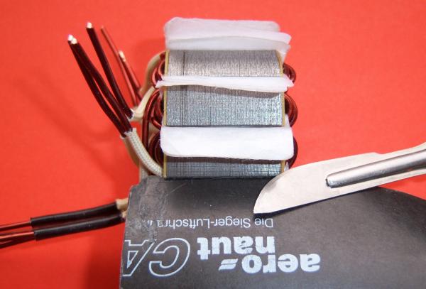
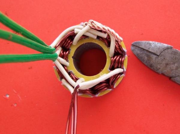
To trim the excess insulation paper, I use the method shown in the picture.
The blade is inserted in the slot and the knife is running on it in order to protect the insulation of the windings.
I add some plastic coated glass fiber tube on the feeding wires (155°C resistance).
Shrinking tubes can also bee used.
The star points need to be stripped from the insulation.
I scrape the insulation of with a scalpel until the copper is shiny.
The shiny ends are wound together.
Put them in place and trim the excess.
Take care to protect the winding underneath during these operations.
Proceed the same way with the second star point.
Solder the wires of the star points together.
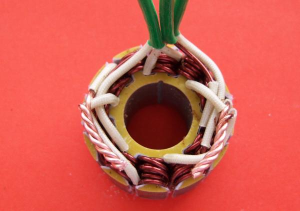
The picture shows the results if stripping and soldering are well done.
Both star points are protected the same way as the feeding wires.
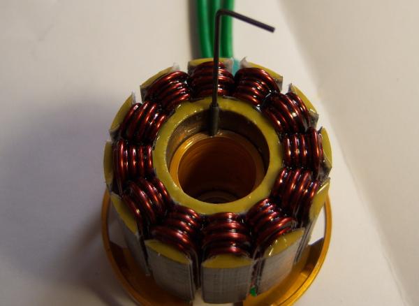
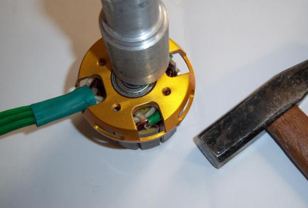
Let’s assemble now the stator on the stator holder and fix it with the anti rotating pin.
I used a 2mm piano wire and a small hammer to drive in the anti rotating pin.
The pin is fitting tightly into the groove.
The anti rotating pin is fixed now.
Alternatively you can make the fixation of the stator package removable.
To do this, you need make a M2 treats in the 1.5mm hole.
Then you add a M2x12 hexagonal head set screw.
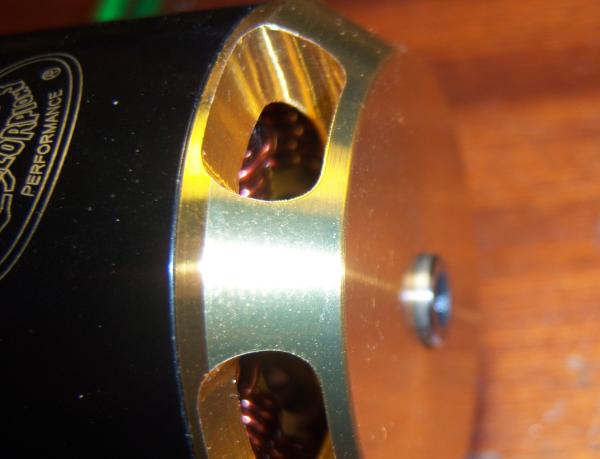
The crew needs to be inserted until there is no remaining over the bearing seat.
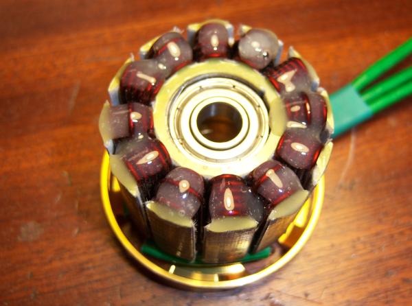
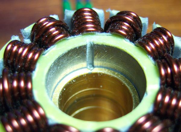
To fix the windings I use the bi-component and 200°C resistant Scorpion glue system.
Alternatively "ENDFEST 300" can be used.
After a short time the glue will run into the slots.
Now lets wait 24 hours until the glue is fully cured.
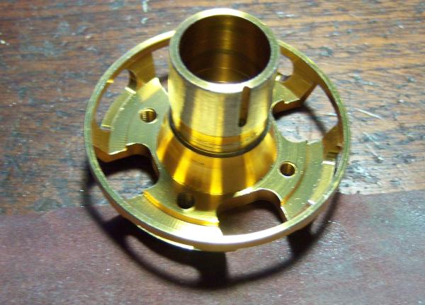
The bearing is inserted into the stator holder backplate.
Never push on the inner Ring to drive it into the bearing seat. Always use the outer bearing ring. Secure with some Loctite (638,620 or 648)
Then add some Loctite (638,620 or 648) or similar to the stator package hole.
Always use a support on the outer bearing ring to drive the bearing into the stator bore.
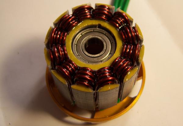
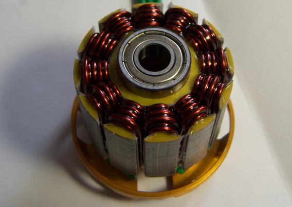
The bearings are mounted now.
The bell is completed and ready to use. The only thing that needs to be added is a bearing trust washer on the shaft between bearing shoulder and bell-bottom.
This washer is not part of the kit. It is strongly recommended to put it in as it will prevent the break in of the hard steel bearing shoulder into the weaker aluminum of the bell-bottom.
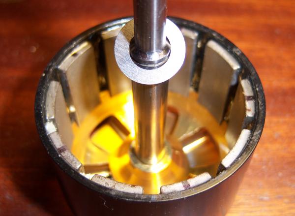
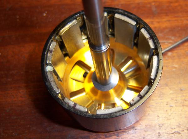
An additional check can be performed on the magnets inside the bell. Use a small magnet to check the polarity.
The test magnet must be attracted and pushed away alternatively on every magnet of the bell.
Then fist assembly is done to check mechanical functions.
The shaft is pushed in to allow the circlips and the spring ring to secure the position of the bell free from axial play.
I had to push my shaft approximately 3 mm out of the bell-bottom plate.
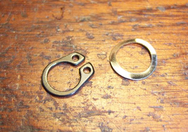
Circlip and the springring shown standalone on this picture.
Circlip is handled ideally with the appropriated pliers.
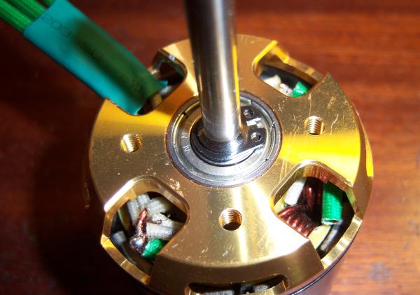
Here you see both mounted on the finished Motor.
The setscrews on the bell-bottom are tightened now. You should secure them with some threat-lock.
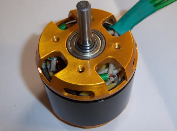
Motor ready to run.
For security, check if there is no short circuit between winding and casing.
If the motor turn quite easy and there is no strong cogging, everything should be ok.
If the restistence between the cogging is strong, in general there is an error in the connections of the windings.
Some hinds for error chasing can be found here!
After the first extended run, recheck the axial play and correct it if necessary.
First run will break-in the mechanics and can result in some increased axial play.
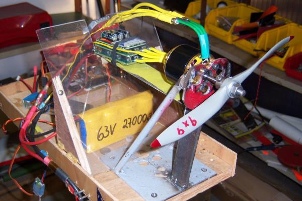
Test run is performed with an YGE controller and a Kontronik JIVE120HV.
The scratches on the back plate and the removed anodizing in the screwholes are a result of an extended test run and are normal and are in no case altering the quality of the motor.
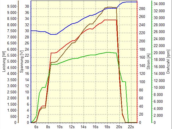
Finally a small performance diagram of another motor from the same series.
Test was performed with 5x1.5YY winding driving a 10x20 speed propeller.
Peak performance was 9500 W during 2 seconds; current 250 A.
Over a period of 10 seconds, the measured power input was over 5000W.
The following windings are tested and can be realized by a skilled winder with some training:
4+4 x(2x1,25)
4+5 x 1,6
5+6 x 1,5
6+6 x 1,4
6+7 x 1,32
7+7 x 1,25
8+8 x 1,18
.....